Control Software for the Inland USB LED Badge
Update 12/14/09: I've moved the code for this program to GitHub.
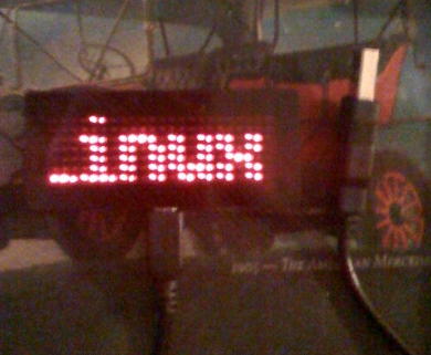
I bought one of these at Micro Center a couple of weeks ago (I just now got around to posting the code -- I've been busy with a few other things) because I wanted to flex my reverse engineering muscles, and work with libhid. I knew there was no way in hell it would come with software for Linux, and at only $14.99 it was quite affordable. Therefore, I went about writing some software to do the job.

0x04d9:0xe002
USB Vendor ID: 0x04d9 Holtek Semiconductor, Inc.
USB Product ID: 0xe002 FURI KEYSHINE USB LED Badge
You can download the source here. The program is written in C, and licensed under the GNU GPLv3. Instructions for how to compile the program are included in the README. You'll find the original documentation (converted to PDF) in the doc directory. Please make sure the badge is connected before running the program.
Requirements:
- GTK+ >= 2.14
- libusb >= 0.1 (Legacy version - libusb 1.x has a much different API)
- libhid >= 0.2.16
- pkg-config, GLib/GDK/GTK+ headers, libusb headers, libhid headers, etc.
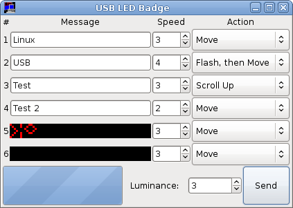
Upon starting the program, you'll see the following window:

If you've used the manufacturer-supplied Delphi progam, then this should seem fairly familiar. If not, it should be fairly obvious what each field is for. The first four fields are text input fields corresponding to the first four messages that can be stored on the device. You simply enter the text you want, choose a speed (the higher the number, the faster the action happens), and an action (e.g. "Move.")
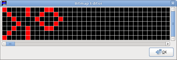
The final two fields are for the two bitmap messages available on the device. If you click on the image, a bitmap editor dialog will appear:

By clicking in the grid, you can set or unset the pixels that comprise the image displayed. If you right click on the grid, you'll get an option to clear the bitmap. When you're done with a bitmap, close the dialog.
The last input item is the "Luminance" spin button. This will set the luminance (intensity) for the LEDs. The default is usually sufficient.
When you click "Send," the data will be sent to the device, and you'll be ready to disconnect the device and use it.
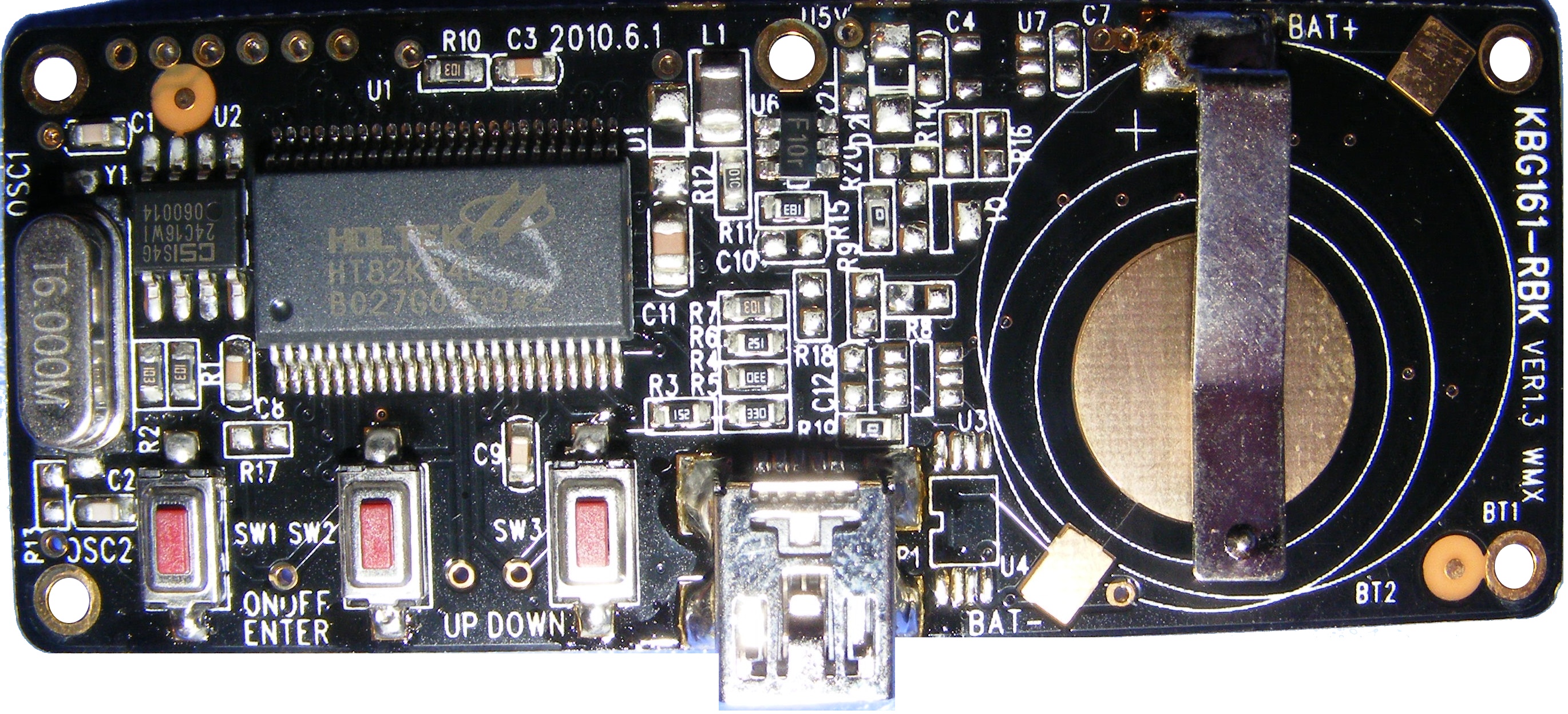
Update (1/10/11): Derek O. provided the following picture of the badge internals. It's apparently driven by a Holtek HT82K94E 8-bit MCU. Click on the image below for a full-size pic! Thanks, Derek!
I had a look at the datasheet (linked above) for this particular MCU, and it would seem to take the USB clock and data lines directly to the chip, which would infer that the memory is on-chip. This raises the question of whether or not the commands sent to the device could be adapted to reprogram it. The instruction set is very straight-forward, although I didn't see any mention of what bits correspond to which instruction. However, the registers and instructions themselves are documented, so it gives some indication of what would be possible.
Holtek has a Winblows-based IDE and emulator available for their microcontrollers, but I'm unaware of any option for Linux at present.
I'd love to dump the on-chip memory. :-P Perhaps I'll revisit it one weekend when I'm looking for something interesting to toy with. ;-)
